Concept art for the TAU spacecraft, a 1980s era study which would have used an interstellar precursor probe to expand the baseline for calculating stellar parallax in support of Astrometry.
The history of astrometry is linked to the history of star catalogues, which gave astronomers reference points for objects in the sky so they could track their movements. This can be dated back to Hipparchus, who around 190 BC used the catalogue of his predecessors Timocharis and Aristillus to discover Earth's precession. In doing so, he also developed the brightness scale still in use today.[1] Hipparchus compiled a catalogue with at least 850 stars and their positions.[2] Hipparchus's successor, Ptolemy, included a catalogue of 1,022 stars in his work the Almagest, giving their location, coordinates, and brightness.[3]
In the 10th century, Abd al-Rahman al-Sufi carried out observations on the stars and described their positions, magnitudes and star color; furthermore, he provided drawings for each constellation, which are depicted in his Book of Fixed Stars. Ibn Yunus observed more than 10,000 entries for the Sun's position for many years using a large astrolabe with a diameter of nearly 1.4 metres. His observations on eclipses were still used centuries later in Simon Newcomb's investigations on the motion of the Moon, while his other observations of the motions of the planets Jupiter and Saturn inspired Laplace's Obliquity of the Ecliptic and Inequalities of Jupiter and Saturn.[4] In the 15th century, the Timurid astronomer Ulugh Beg compiled the Zij-i-Sultani, in which he catalogued 1,019 stars. Like the earlier catalogs of Hipparchus and Ptolemy, Ulugh Beg's catalogue is estimated to have been precise to within approximately 20 minutes of arc.[5]
This is the oldest branch of astronomy and dates back to antiquity. Observations of celestial objects have been, and continue to be, important for religious and astrological purposes, as well as for timekeeping and navigation. The science of actually measuring positions of celestial objects in the sky is known as astrometry.
The coordinates of celestial objects such as stars and galaxies are tabulated in a star catalog, which gives the position for a particular year. However, the combined effects of axial precession and nutation will cause the coordinates to change slightly over time. The effects of these changes in Earth's motion are compensated by the periodic publication of revised catalogs.
To determine the position of the Sun and planets, an astronomical ephemeris (a table of values that gives the positions of astronomical objects in the sky at a given time) is used, which can then be converted into suitable real-world coordinates.
The physics convention. Spherical coordinates (r, θ, φ) as commonly used: (ISO80000-2:2019): radial distance r (slant distance to origin), polar angle θ (theta) (angle with respect to positive polar axis), and azimuthal angle φ (phi) (angle of rotation from the initial meridian plane). This is the convention followed in this article.
In mathematics, a spherical coordinate system is a coordinate system for three-dimensional space where the position of a given point in space is specified by three numbers, (r, θ, φ): the radial distance of the radial liner connecting the point to the fixed point of origin (which is located on a fixed polar axis, or zenith direction axis, or z-axis); the polar angle θ of the radial line r; and the azimuthal angle φ of the radial line r.
The polar angle θ is measured between the z-axis and the radial line r. The azimuthal angle φ is measured between the orthogonal projection of the radial line r onto the reference x-y-plane—which is orthogonal to the z-axis and passes through the fixed point of origin—and either of the fixed x-axis or y-axis, both of which are orthogonal to the z-axis and to each other. (See graphic re the "physics convention".)
Once the radius is fixed, the three coordinates (r, θ, φ), known as a 3-tuple, provide a coordinate system on a sphere, typically called the spherical polar coordinates. Nota bene: the physics convention is followed in this article; (See both graphics re "physics convention" and re "mathematics convention").
The radial distance from the fixed point of origin is also called the radius, or radial line, or radial coordinate. The polar angle may be called inclination angle, zenith angle, normal angle, or the colatitude. The user may choose to ignore the inclination angle and use the elevation angle instead, which is measured upward between the reference plane and the radial line—i.e., from the reference plane upward (towards to the positive z-axis) to the radial line. The depression angle is the negative of the elevation angle. (See graphic re the "physics convention"—not "mathematics convention".)
Both the use of symbols and the naming order of tuple coordinates differ among the several sources and disciplines. This article will use the ISO convention[1] frequently encountered in physics, where the naming tuple gives the order as: radial distance, polar angle, azimuthal angle, or . (See graphic re the "physics convention".) In contrast, the conventions in many mathematics books and texts give the naming order differently as: radial distance, "azimuthal angle", "polar angle", and or —which switches the uses and meanings of symbols θ and φ. Other conventions may also be used, such as r for a radius from the z-axis that is not from the point of origin. Particular care must be taken to check the meaning of the symbols.
The mathematics convention. Spherical coordinates (r, θ, φ) as typically used: radial distance r, azimuthal angle θ, and polar angle φ. + The meanings of θ and φ have been swapped—compared to the physics convention. The 'south'-direction x-axis is depicted but the 'north'-direction x-axis is not. (As in physics, ρ (rho) is often used instead of r to avoid confusion with the value r in cylindrical and 2D polar coordinates.)
According to the conventions of geographical coordinate systems, positions are measured by latitude, longitude, and height (altitude). There are a number of celestial coordinate systems based on different fundamental planes and with different terms for the various coordinates. The spherical coordinate systems used in mathematics normally use radians rather than degrees; (note 90 degrees equals π/2 radians). And these systems of the mathematics convention may measure the azimuthal angle counterclockwise (i.e., from the south direction x-axis, or 180°, towards the east direction y-axis, or +90°)—rather than measure clockwise (i.e., from the north direction x-axis, or 0°, towards the east direction y-axis, or +90°), as done in the horizontal coordinate system.[2](See graphic re "mathematics convention".)
To define a spherical coordinate system, one must designate an origin point in space, O, and two orthogonal directions: the zenith reference direction and the azimuth reference direction. These choices determine a reference plane that is typically defined as containing the point of origin and the x– and y–axes, either of which may be designated as the azimuth reference direction. The reference plane is perpendicular (orthogonal) to the zenith direction, and typically is desiginated "horizontal" to the zenith direction's "vertical". The spherical coordinates of a point P then are defined as follows:
The radius or radial distance is the Euclidean distance from the origin O to P.
The inclination (or polar angle) is the signed angle from the zenith reference direction to the line segment OP. (Elevation may be used as the polar angle instead of inclination; see below.)
The azimuth (or azimuthal angle) is the signed angle measured from the azimuth reference direction to the orthogonal projection of the radial line segment OP on the reference plane.
The sign of the azimuth is determined by designating the rotation that is the positive sense of turning about the zenith. This choice is arbitrary, and is part of the coordinate system definition. (If the inclination is either zero or 180 degrees (= π radians), the azimuth is arbitrary. If the radius is zero, both azimuth and inclination are arbitrary.)
The elevation is the signed angle from the x-y reference plane to the radial line segment OP, where positive angles are designated as upward, towards the zenith reference. Elevation is 90 degrees (= π/2 radians) minus inclination. Thus, if the inclination is 60 degrees (= π/3 radians), then the elevation is 30 degrees (= π/6 radians).
Sidereal time vs solar time. Above left: a distant star (the small orange star) and the Sun are at culmination, on the local meridian m. Centre: only the distant star is at culmination (a mean sidereal day). Right: a few minutes later the Sun is on the local meridian again. A solar day is complete.
Solar time is measured by the apparent diurnal motion of the Sun. Local noon in apparent solar time is the moment when the Sun is exactly due south or north (depending on the observer's latitude and the season). A mean solar day (what we normally measure as a "day") is the average time between local solar noons ("average" since this varies slightly over a year).
Earth makes one rotation around its axis each sidereal day; during that time it moves a short distance (about 1°) along its orbit around the Sun. So after a sidereal day has passed, Earth still needs to rotate slightly more before the Sun reaches local noon according to solar time. A mean solar day is, therefore, nearly 4 minutes longer than a sidereal day.
The stars are so far away that Earth's movement along its orbit makes nearly no difference to their apparent direction (except for the nearest stars if measured with extreme accuracy; see parallax), and so they return to their highest point at the same time each sidereal day.
Another way to understand this difference is to notice that, relative to the stars, as viewed from Earth, the position of the Sun at the same time each day appears to move around Earth once per year. A year has about 365.24 solar days but 366.24 sidereal days. Therefore, there is one fewer solar day per year than there are sidereal days, similar to an observation of the coin rotation paradox.[5] This makes a sidereal day approximately 365.24/366.24 times the length of the 24-hour solar day.
A diagram of the Earth–Moon system showing how the tidal bulge is pushed ahead by Earth's rotation. This offset bulge exerts a net torque on the Moon, boosting it while slowing Earth's rotation.
The plane of the Moon's orbit around Earth lies close to the plane of Earth's orbit around the Sun (the ecliptic), rather than in the plane of the Earth's rotation (the equator) as is usually the case with planetary satellites. The mass of the Moon is sufficiently large, and it is sufficiently close, to raise tides in the matter of Earth. Foremost among such matter, the water of the oceans bulges out both towards and away from the Moon. If the material of the Earth responded immediately, there would be a bulge directly toward and away from the Moon. In the solid Earth tides, there is a delayed response due to the dissipation of tidal energy. The case for the oceans is more complicated, but there is also a delay associated with the dissipation of energy since the Earth rotates at a faster rate than the Moon's orbital angular velocity. This lunitidal interval in the responses causes the tidal bulge to be carried forward. Consequently, the line through the two bulges is tilted with respect to the Earth-Moon direction exerting torque between the Earth and the Moon. This torque boosts the Moon in its orbit and slows the rotation of Earth.
As a result of this process, the mean solar day, which has to be 86,400 equal seconds, is actually getting longer when measured in SIseconds with stable atomic clocks. (The SI second, when adopted, was already a little shorter than the current value of the second of mean solar time.[12]) The small difference accumulates over time, which leads to an increasing difference between our clock time (Universal Time) on the one hand, and International Atomic Time and ephemeris time on the other hand: see ΔT. This led to the introduction of the leap second in 1972 [13] to compensate for differences in the bases for time standardization.
In addition to the effect of the ocean tides, there is also a tidal acceleration due to flexing of Earth's crust, but this accounts for only about 4% of the total effect when expressed in terms of heat dissipation.[14]
Ecliptic
From Wikipedia, the free encyclopedia
As seen from the orbiting Earth, the Sunappears to move with respect to the fixed stars, and the ecliptic is the yearly path the Sun follows on the celestial sphere. This process repeats itself in a cycle lasting a little over 365 days.
The ecliptic is the apparent path of the Sun throughout the course of a year.[4]
Because Earth takes one year to orbit the Sun, the apparent position of the Sun takes one year to make a complete circuit of the ecliptic. With slightly more than 365 days in one year, the Sun moves a little less than 1° eastward[5] every day. This small difference in the Sun's position against the stars causes any particular spot on Earth's surface to catch up with (and stand directly north or south of) the Sun about four minutes later each day than it would if Earth did not orbit; a day on Earth is therefore 24 hours long rather than the approximately 23-hour 56-minute sidereal day. Again, this is a simplification, based on a hypothetical Earth that orbits at uniform speed around the Sun. The actual speed with which Earth orbits the Sun varies slightly during the year, so the speed with which the Sun seems to move along the ecliptic also varies. For example, the Sun is north of the celestial equator for about 185 days of each year, and south of it for about 180 days.[6] The variation of orbital speed accounts for part of the equation of time.[7]
Because of the movement of Earth around the Earth–Moon center of mass, the apparent path of the Sun wobbles slightly, with a period of about one month. Because of further perturbations by the other planets of the Solar System, the Earth–Moon barycenter wobbles slightly around a mean position in a complex fashion.
In 1609, Johannes Kepler correctly suggested that the influence of the Moon influences the tides,[c] which he compared to magnetic attraction[20][4][21][22] basing his argument upon ancient observations and correlations.
In 1616, Galileo Galilei wrote Discourse on the Tides.[23] He strongly and mockingly rejects the lunar theory of the tides,[21][4] and tries to explain the tides as the result of the Earth's rotation and revolution around the Sun, believing that the oceans moved like water in a large basin: as the basin moves, so does the water.[24] Therefore, as the Earth revolves, the force of the Earth's rotation causes the oceans to "alternately accelerate and retardate".[25] His view on the oscillation and "alternately accelerated and retardated" motion of the Earth's rotation is a "dynamic process" that deviated from the previous dogma, which proposed "a process of expansion and contraction of seawater."[26] However, Galileo's theory was erroneous.[23] In subsequent centuries, further analysis led to the current tidal physics. Galileo tried to use his tidal theory to prove the movement of the Earth around the Sun. Galileo theorized that because of the Earth's motion, borders of the oceans like the Atlantic and Pacific would show one high tide and one low tide per day. The Mediterranean Sea had two high tides and low tides, though Galileo argued that this was a product of secondary effects and that his theory would hold in the Atlantic. However, Galileo's contemporaries noted that the Atlantic also had two high tides and low tides per day, which led to Galileo omitting this claim from his 1632 Dialogue.[27]
René Descartes theorized that the tides (alongside the movement of planets, etc.) were caused by aetheric vortices, without reference to Kepler's theories of gravitation by mutual attraction; this was extremely influential, with numerous followers of Descartes expounding on this theory throughout the 17th century, particularly in France.[28] However, Descartes and his followers acknowledged the influence of the Moon, speculating that pressure waves from the Moon via the aether were responsible for the correlation.[5][29][6][30]
Newton's three-body model
Newton, in the Principia, provides a correct explanation for the tidal force, which can be used to explain tides on a planet covered by a uniform ocean but which takes no account of the distribution of the continents or ocean bathymetry.[31]
While Newton explained the tides by describing the tide-generating forces and Daniel Bernoulli gave a description of the static reaction of the waters on Earth to the tidal potential, the dynamic theory of tides, developed by Pierre-Simon Laplace in 1775,[32] describes the ocean's real reaction to tidal forces.[33] Laplace's theory of ocean tides takes into account friction, resonance and natural periods of ocean basins. It predicts the large amphidromic systems in the world's ocean basins and explains the oceanic tides that are actually observed.[34]
Spin-stabilized magnetic levitation
From Wikipedia, the free encyclopedia
Duration: 2 minutes and 28 seconds.2:28Subtitles available.CCA brief demonstration and small explanation featuring a Levitronbranded levitating top device which works based upon the phenomenon of spin-stabilized magnetic levitation.
Spin-stabilized magnetic levitation is a phenomenon of magnetic levitation whereby a spinning magnet or array of magnets (typically as a top) is levitated via magnetic forces above another magnet or array of magnets, and stabilised by gyroscopic effect due to a spin rate that is neither too fast, nor too slow to allow for a necessary precession.
The phenomenon was originally discovered through invention by Vermont inventor Roy M. Harrigan in the 1970s. On May 3, 1983 Harrigan received a United States patent for his original levitation device based upon this phenomenon he discovered.[1][2] Independent of Harrigan, a Pennsylvanian inventor named Joseph Chieffo made the same discovery in 1984 employing a flat base magnet, a geometry that proved a significant change over his predecessor's patented design which relies upon a dish shaped mounting of magnets for the base. Chieffo's design, publicized in a 1991 edition of the periodical "Magnets In Your Future",[3] further differed from Harrigan's in its incorporation of an un-weighted top.[4][5] Harrigan's technology, either solely or in conjunction with Chieffo's published flat-base variation, provided the basis for the development of mass marketed levitating toy tops sold under the brand name, 'Levitron'.
In 2012[6] and 2014[7] Max Michaelis reported operating Levitron brand magnetic tops at inclination angles of 45° and 90° (i.e. with the spin axis, horizontal) after employing novel configurations for the supporting magnetic fields.
Earnshaw's theorem does not allow for a static configuration of permanent magnets to stably levitate another permanent magnet or materials that are paramagnetic or ferromagnetic against gravity. This theorem does not apply to devices consisting of a properly configured magnetic base and corresponding magnetic top, however, because the non-static nature of the spinning magnetic top within a threshold of lower and upper RPM spin rates acts as a balanced precessing gyroscope to prevent the poles of its magnetic field from fully aligning themselves in the same direction as those of the primary supporting toroidal field of the magnetic base (i.e.: via the top flipping). In a vertical orientated spin axis configuration this gyroscopic property with its necessary precession allows it to respond dynamically to the field direction of the central magnetic gradient of the toroidally shaped field of its base magnet(s) and thereby remain self-centered in a restorative manner, levitating about an elevated central point within the base magnetic field where the forces acting on the top (gravitational, magnetic, and gyroscopic) are in a stable equilibrium thus allowing the top to stay hovering while resting in an energy minimum well.[8] (see: magnetic levitation)
In the laboratory, experimental setups are able to levitate tops for indefinite periods by measuring the spin rate and maintaining it using a drive coil. However, variations in temperature can affect the stability, and without ambient temperature control the top will eventually fall after hours or days due to the temperature coefficient of the magnets.[8]
Inclined or horizontal spin axis levitation is accomplished by superposing a “macro-trap” on the precessional “micro-trap” first described by Sir Michael Berry[9] and Simon, Heflinger and Ridgway.[8] The macro-trap is generated by a combination of two magnetic “V”s as well as a puller magnet, situated directly above the Levitron. The puller acts like the string of a pendulum.
Description
The force on an electric charge depends on its location, speed, and direction; two vector fields are used to describe this force.[2]: ch1 The first is the electric field, which describes the force acting on a stationary charge and gives the component of the force that is independent of motion. The magnetic field, in contrast, describes the component of the force that is proportional to both the speed and direction of charged particles.[2]: ch13 The field is defined by the Lorentz force law and is, at each instant, perpendicular to both the motion of the charge and the force it experiences.
There are two different, but closely related vector fields which are both sometimes called the "magnetic field" written B and H.[note 1] While both the best names for these fields and exact interpretation of what these fields represent has been the subject of long running debate, there is wide agreement about how the underlying physics work.[7] Historically, the term "magnetic field" was reserved for H while using other terms for B, but many recent textbooks use the term "magnetic field" to describe B as well as or in place of H.[note 2] There are many alternative names for both (see sidebars).
The B-field
Finding the magnetic force
A charged particle that is moving with velocity v in a magnetic field B will feel a magnetic force F. Since the magnetic force always pulls sideways to the direction of motion, the particle moves in a circle.
Since these three vectors are related to each other by a cross product, the direction of this force can be found using the right hand rule.
The magnetic field vector B at any point can be defined as the vector that, when used in the Lorentz force law, correctly predicts the force on a charged particle at that point:[10][11]: 204
Here F is the force on the particle, q is the particle's electric charge, v, is the particle's velocity, and × denotes the cross product. The direction of force on the charge can be determined by a mnemonic known as the right-hand rule (see the figure).[note 3] Using the right hand, pointing the thumb in the direction of the current, and the fingers in the direction of the magnetic field, the resulting force on the charge points outwards from the palm. The force on a negatively charged particle is in the opposite direction. If both the speed and the charge are reversed then the direction of the force remains the same. For that reason a magnetic field measurement (by itself) cannot distinguish whether there is a positive charge moving to the right or a negative charge moving to the left. (Both of these cases produce the same current.) On the other hand, a magnetic field combined with an electric field can distinguish between these, see Hall effect below.
The first term in the Lorentz equation is from the theory of electrostatics, and says that a particle of charge q in an electric field E experiences an electric force:
Using the definition of the cross product, the magnetic force can also be written as a scalar equation:[10]: 357
where Fmagnetic, v, and B are the scalar magnitude of their respective vectors, and θ is the angle between the velocity of the particle and the magnetic field. The vector B is defined as the vector field necessary to make the Lorentz force law correctly describe the motion of a charged particle. In other words,[10]: 173–4
[T]he command, "Measure the direction and magnitude of the vector B at such and such a place," calls for the following operations: Take a particle of known charge q. Measure the force on q at rest, to determine E. Then measure the force on the particle when its velocity is v; repeat with v in some other direction. Now find a B that makes the Lorentz force law fit all these results—that is the magnetic field at the place in question.
The B field can also be defined by the torque on a magnetic dipole, m.[12]: 174
The SI unit of B is tesla (symbol: T).[note 4] The Gaussian-cgs unit of B is the gauss (symbol: G). (The conversion is 1 T ≘ 10000 G.[13][14]) One nanotesla corresponds to 1 gamma (symbol: γ).[14]
Left: the direction of magnetic field lines represented by iron filings sprinkled on paper placed above a bar magnet. Right: compass needles point in the direction of the local magnetic field, towards a magnet's south pole and away from its north pole.
The field can be visualized by a set of magnetic field lines, that follow the direction of the field at each point. The lines can be constructed by measuring the strength and direction of the magnetic field at a large number of points (or at every point in space). Then, mark each location with an arrow (called a vector) pointing in the direction of the local magnetic field with its magnitude proportional to the strength of the magnetic field. Connecting these arrows then forms a set of magnetic field lines. The direction of the magnetic field at any point is parallel to the direction of nearby field lines, and the local density of field lines can be made proportional to its strength. Magnetic field lines are like streamlines in fluid flow, in that they represent a continuous distribution, and a different resolution would show more or fewer lines.
An advantage of using magnetic field lines as a representation is that many laws of magnetism (and electromagnetism) can be stated completely and concisely using simple concepts such as the "number" of field lines through a surface. These concepts can be quickly "translated" to their mathematical form. For example, the number of field lines through a given surface is the surface integral of the magnetic field.[10]: 237
Various phenomena "display" magnetic field lines as though the field lines were physical phenomena. For example, iron filings placed in a magnetic field form lines that correspond to "field lines".[note 5] Magnetic field "lines" are also visually displayed in polar auroras, in which plasma particle dipole interactions create visible streaks of light that line up with the local direction of Earth's magnetic field.
Field lines can be used as a qualitative tool to visualize magnetic forces. In ferromagnetic substances like iron and in plasmas, magnetic forces can be understood by imagining that the field lines exert a tension, (like a rubber band) along their length, and a pressure perpendicular to their length on neighboring field lines. "Unlike" poles of magnets attract because they are linked by many field lines; "like" poles repel because their field lines do not meet, but run parallel, pushing on each other.
Permanent magnets are objects that produce their own persistent magnetic fields. They are made of ferromagnetic materials, such as iron and nickel, that have been magnetized, and they have both a north and a south pole.
The magnetic field of permanent magnets can be quite complicated, especially near the magnet. The magnetic field of a small[note 6] straight magnet is proportional to the magnet's strength (called its magnetic dipole momentm). The equations are non-trivial and depend on the distance from the magnet and the orientation of the magnet. For simple magnets, m points in the direction of a line drawn from the south to the north pole of the magnet. Flipping a bar magnet is equivalent to rotating its m by 180 degrees.
The magnetic field of larger magnets can be obtained by modeling them as a collection of a large number of small magnets called dipoles each having their own m. The magnetic field produced by the magnet then is the net magnetic field of these dipoles; any net force on the magnet is a result of adding up the forces on the individual dipoles.
There are two simplified models for the nature of these dipoles: the magnetic pole model and the Amperian loop model. These two models produce two different magnetic fields, H and B. Outside a material, though, the two are identical (to a multiplicative constant) so that in many cases the distinction can be ignored. This is particularly true for magnetic fields, such as those due to electric currents, that are not generated by magnetic materials.
A realistic model of magnetism is more complicated than either of these models; neither model fully explains why materials are magnetic. The monopole model has no experimental support. The Amperian loop model explains some, but not all of a material's magnetic moment. The model predicts that the motion of electrons within an atom are connected to those electrons' orbital magnetic dipole moment, and these orbital moments do contribute to the magnetism seen at the macroscopic level. However, the motion of electrons is not classical, and the spin magnetic moment of electrons (which is not explained by either model) is also a significant contribution to the total moment of magnets.
The magnetic pole model: two opposing poles, North (+) and South (−), separated by a distance d produce a H-field (lines).
Historically, early physics textbooks would model the force and torques between two magnets as due to magnetic poles repelling or attracting each other in the same manner as the Coulomb force between electric charges. At the microscopic level, this model contradicts the experimental evidence, and the pole model of magnetism is no longer the typical way to introduce the concept.[11]: 258 However, it is still sometimes used as a macroscopic model for ferromagnetism due to its mathematical simplicity.[17]
In this model, a magnetic H-field is produced by fictitious magnetic charges that are spread over the surface of each pole. These magnetic charges are in fact related to the magnetization field M. The H-field, therefore, is analogous to the electric fieldE, which starts at a positive electric charge and ends at a negative electric charge. Near the north pole, therefore, all H-field lines point away from the north pole (whether inside the magnet or out) while near the south pole all H-field lines point toward the south pole (whether inside the magnet or out). Too, a north pole feels a force in the direction of the H-field while the force on the south pole is opposite to the H-field.
In the magnetic pole model, the elementary magnetic dipole m is formed by two opposite magnetic poles of pole strength qm separated by a small distance vector d, such that m = qmd. The magnetic pole model predicts correctly the field H both inside and outside magnetic materials, in particular the fact that H is opposite to the magnetization field M inside a permanent magnet.
Since it is based on the fictitious idea of a magnetic charge density, the pole model has limitations. Magnetic poles cannot exist apart from each other as electric charges can, but always come in north–south pairs. If a magnetized object is divided in half, a new pole appears on the surface of each piece, so each has a pair of complementary poles. The magnetic pole model does not account for magnetism that is produced by electric currents, nor the inherent connection between angular momentum and magnetism.
The pole model usually treats magnetic charge as a mathematical abstraction, rather than a physical property of particles. However, a magnetic monopole is a hypothetical particle (or class of particles) that physically has only one magnetic pole (either a north pole or a south pole). In other words, it would possess a "magnetic charge" analogous to an electric charge. Magnetic field lines would start or end on magnetic monopoles, so if they exist, they would give exceptions to the rule that magnetic field lines neither start nor end. Some theories (such as Grand Unified Theories) have predicted the existence of magnetic monopoles, but so far, none have been observed.
A current loop (ring) that goes into the page at the x and comes out at the dot produces a B-field (lines). As the radius of the current loop shrinks, the fields produced become identical to an abstract "magnetostatic dipole" (represented by an arrow pointing to the right).
In the model developed by Ampere, the elementary magnetic dipole that makes up all magnets is a sufficiently small Amperian loop with current I and loop area A. The dipole moment of this loop is m = IA.
These magnetic dipoles produce a magnetic B-field.
The magnetic field of a magnetic dipole is depicted in the figure. From outside, the ideal magnetic dipole is identical to that of an ideal electric dipole of the same strength. Unlike the electric dipole, a magnetic dipole is properly modeled as a current loop having a current I and an area a. Such a current loop has a magnetic moment of
where the direction of m is perpendicular to the area of the loop and depends on the direction of the current using the right-hand rule. An ideal magnetic dipole is modeled as a real magnetic dipole whose area a has been reduced to zero and its current I increased to infinity such that the product m = Ia is finite. This model clarifies the connection between angular momentum and magnetic moment, which is the basis of the Einstein–de Haas effectrotation by magnetization and its inverse, the Barnett effect or magnetization by rotation.[18] Rotating the loop faster (in the same direction) increases the current and therefore the magnetic moment, for example.
Interactions with electric currents
Currents of electric charges both generate a magnetic field and feel a force due to magnetic B-fields.
Magnetic field due to moving charges and electric currents
Right hand grip rule: a current flowing in the direction of the white arrow produces a magnetic field shown by the red arrows.
All moving charged particles produce magnetic fields. Moving point charges, such as electrons, produce complicated but well known magnetic fields that depend on the charge, velocity, and acceleration of the particles.[20]
Magnetic field lines form in concentric circles around a cylindrical current-carrying conductor, such as a length of wire. The direction of such a magnetic field can be determined by using the "right-hand grip rule" (see figure at right). The strength of the magnetic field decreases with distance from the wire. (For an infinite length wire the strength is inversely proportional to the distance.)
A Solenoid with electric current running through it behaves like a magnet.
Bending a current-carrying wire into a loop concentrates the magnetic field inside the loop while weakening it outside. Bending a wire into multiple closely spaced loops to form a coil or "solenoid" enhances this effect. A device so formed around an iron core may act as an electromagnet, generating a strong, well-controlled magnetic field. An infinitely long cylindrical electromagnet has a uniform magnetic field inside, and no magnetic field outside. A finite length electromagnet produces a magnetic field that looks similar to that produced by a uniform permanent magnet, with its strength and polarity determined by the current flowing through the coil.
The magnetic field generated by a steady current I (a constant flow of electric charges, in which charge neither accumulates nor is depleted at any point)[note 8] is described by the Biot–Savart law:[21]: 224
where the integral sums over the wire length where vector dℓ is the vector line element with direction in the same sense as the current I, μ0 is the magnetic constant, r is the distance between the location of dℓ and the location where the magnetic field is calculated, and r̂ is a unit vector in the direction of r. For example, in the case of a sufficiently long, straight wire, this becomes:
where r = |r|. The direction is tangent to a circle perpendicular to the wire according to the right hand rule.[21]: 225
A changing magnetic field, such as a magnet moving through a conducting coil, generates an electric field (and therefore tends to drive a current in such a coil). This is known as Faraday's law and forms the basis of many electrical generators and electric motors. Mathematically, Faraday's law is:
where is the electromotive force (or EMF, the voltage generated around a closed loop) and Φ is the magnetic flux—the product of the area times the magnetic field normal to that area. (This definition of magnetic flux is why B is often referred to as magnetic flux density.)[35]: 210 The negative sign represents the fact that any current generated by a changing magnetic field in a coil produces a magnetic field that opposes the change in the magnetic field that induced it. This phenomenon is known as Lenz's law. This integral formulation of Faraday's law can be converted[note 13] into a differential form, which applies under slightly different conditions.
A sketch of Earth's magnetic field representing the source of the field as a magnet. The south pole of the magnetic field is near the geographic north pole of the Earth.
The Earth's magnetic field is produced by convection of a liquid iron alloy in the outer core. In a dynamo process, the movements drive a feedback process in which electric currents create electric and magnetic fields that in turn act on the currents.[44]
The field at the surface of the Earth is approximately the same as if a giant bar magnet were positioned at the center of the Earth and tilted at an angle of about 11° off the rotational axis of the Earth (see the figure).[45] The north pole of a magnetic compass needle points roughly north, toward the North Magnetic Pole. However, because a magnetic pole is attracted to its opposite, the North Magnetic Pole is actually the south pole of the geomagnetic field. This confusion in terminology arises because the pole of a magnet is defined by the geographical direction it points.[46]
Earth's magnetic field is not constant—the strength of the field and the location of its poles vary.[47] Moreover, the poles periodically reverse their orientation in a process called geomagnetic reversal. The most recent reversal occurred 780,000 years ago.[48]
The rotating magnetic field is a key principle in the operation of alternating-current motors. A permanent magnet in such a field rotates so as to maintain its alignment with the external field.
Magnetic torque is used to drive electric motors. In one simple motor design, a magnet is fixed to a freely rotating shaft and subjected to a magnetic field from an array of electromagnets. By continuously switching the electric current through each of the electromagnets, thereby flipping the polarity of their magnetic fields, like poles are kept next to the rotor; the resultant torque is transferred to the shaft.
A rotating magnetic field can be constructed using two orthogonal coils with 90 degrees phase difference in their AC currents. However, in practice such a system would be supplied through a three-wire arrangement with unequal currents.
This inequality would cause serious problems in standardization of the conductor size and so, to overcome it, three-phase systems are used where the three currents are equal in magnitude and have 120 degrees phase difference. Three similar coils having mutual geometrical angles of 120 degrees create the rotating magnetic field in this case. The ability of the three-phase system to create a rotating field, utilized in electric motors, is one of the main reasons why three-phase systems dominate the world's electrical power supply systems.
Synchronous motors use DC-voltage-fed rotor windings, which lets the excitation of the machine be controlled—and induction motors use short-circuited rotors (instead of a magnet) following the rotating magnetic field of a multicoiled stator. The short-circuited turns of the rotor develop eddy currents in the rotating field of the stator, and these currents in turn move the rotor by the Lorentz force.
The Italian physicist Galileo Ferraris and the Serbian-American electrical engineerNikola Tesla independently researched the use of rotating magnetic fields in electric motors. In 1888, Ferraris published his research in a paper to the Royal Academy of Sciences in Turin and Tesla gained U.S. patent 381,968 for his work.
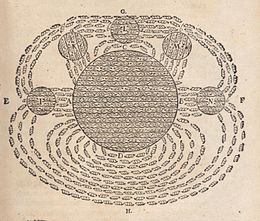
One of the first drawings of a magnetic field, by René Descartes, 1644, showing the Earth attracting lodestones. It illustrated his theory that magnetism was caused by the circulation of tiny helical particles, "threaded parts", through threaded pores in magnets.
Early developments
While magnets and some properties of magnetism were known to ancient societies, the research of magnetic fields began in 1269 when French scholar Petrus Peregrinus de Maricourt mapped out the magnetic field on the surface of a spherical magnet using iron needles. Noting the resulting field lines crossed at two points he named those points "poles" in analogy to Earth's poles. He also articulated the principle that magnets always have both a north and south pole, no matter how finely one slices them.[54][note 14]
Almost three centuries later, William Gilbert of Colchester replicated Petrus Peregrinus' work and was the first to state explicitly that Earth is a magnet.[55]: 34 Published in 1600, Gilbert's work, De Magnete, helped to establish magnetism as a science.
In 1750, John Michell stated that magnetic poles attract and repel in accordance with an inverse square law[55]: 56 Charles-Augustin de Coulomb experimentally verified this in 1785 and stated explicitly that north and south poles cannot be separated.[55]: 59 Building on this force between poles, Siméon Denis Poisson (1781–1840) created the first successful model of the magnetic field, which he presented in 1824.[55]: 64 In this model, a magnetic H-field is produced by magnetic poles and magnetism is due to small pairs of north–south magnetic poles.
Three discoveries in 1820 challenged this foundation of magnetism. Hans Christian Ørsted demonstrated that a current-carrying wire is surrounded by a circular magnetic field.[note 15][56] Then André-Marie Ampère showed that parallel wires with currents attract one another if the currents are in the same direction and repel if they are in opposite directions.[55]: 87 [57] Finally, Jean-Baptiste Biot and Félix Savart announced empirical results about the forces that a current-carrying long, straight wire exerted on a small magnet, determining the forces were inversely proportional to the perpendicular distance from the wire to the magnet.[58][55]: 86 Laplace later deduced a law of force based on the differential action of a differential section of the wire,[58][59] which became known as the Biot–Savart law, as Laplace did not publish his findings.[60]
Extending these experiments, Ampère published his own successful model of magnetism in 1825. In it, he showed the equivalence of electrical currents to magnets[55]: 88 and proposed that magnetism is due to perpetually flowing loops of current instead of the dipoles of magnetic charge in Poisson's model.[note 16] Further, Ampère derived both Ampère's force law describing the force between two currents and Ampère's law, which, like the Biot–Savart law, correctly described the magnetic field generated by a steady current. Also in this work, Ampère introduced the term electrodynamics to describe the relationship between electricity and magnetism.[55]: 88–92
In 1831, Michael Faraday discovered electromagnetic induction when he found that a changing magnetic field generates an encircling electric field, formulating what is now known as Faraday's law of induction.[55]: 189–192 Later, Franz Ernst Neumann proved that, for a moving conductor in a magnetic field, induction is a consequence of Ampère's force law.[55]: 222 In the process, he introduced the magnetic vector potential, which was later shown to be equivalent to the underlying mechanism proposed by Faraday.[55]: 225
In 1850, Lord Kelvin, then known as William Thomson, distinguished between two magnetic fields now denoted H and B. The former applied to Poisson's model and the latter to Ampère's model and induction.[55]: 224 Further, he derived how H and B relate to each other and coined the term permeability.[55]: 245 [61]
In 1887, Tesla developed an induction motor that ran on alternating current. The motor used polyphase current, which generated a rotating magnetic field to turn the motor (a principle that Tesla claimed to have conceived in 1882).[64][65][66] Tesla received a patent for his electric motor in May 1888.[67][68] In 1885, Galileo Ferraris independently researched rotating magnetic fields and subsequently published his research in a paper to the Royal Academy of Sciences in Turin, just two months before Tesla was awarded his patent, in March 1888.[69]
The twentieth century showed that classical electrodynamics is already consistent with special relativity, and extended classical electrodynamics to work with quantum mechanics. Albert Einstein, in his paper of 1905 that established relativity, showed that both the electric and magnetic fields are part of the same phenomena viewed from different reference frames. Finally, the emergent field of quantum mechanics was merged with electrodynamics to form quantum electrodynamics, which first formalized the notion that electromagnetic field energy is quantized in the form of photons.
Magnetic hysteresis occurs when an external magnetic field is applied to a ferromagnet such as iron and the atomic dipoles align themselves with it. Even when the field is removed, part of the alignment will be retained: the material has become magnetized. Once magnetized, the magnet will stay magnetized indefinitely. To demagnetize it requires heat or a magnetic field in the opposite direction. This is the effect that provides the element of memory in a hard disk drive.
The relationship between field strength H and magnetizationM is not linear in such materials. If a magnet is demagnetized (H = M = 0) and the relationship between H and M is plotted for increasing levels of field strength, M follows the initial magnetization curve. This curve increases rapidly at first and then approaches an asymptote called magnetic saturation. If the magnetic field is now reduced monotonically, M follows a different curve. At zero field strength, the magnetization is offset from the origin by an amount called the remanence. If the H-M relationship is plotted for all strengths of applied magnetic field the result is a hysteresis loop called the main loop. The width of the middle section along the H axis is twice the coercivity of the material.[1]: Chapter 1
Magnetic hysteresis loops are not exclusive to materials with ferromagnetic ordering. Other magnetic orderings, such as spin glass ordering, also exhibit this phenomenon.[2]
The phenomenon of hysteresis in ferromagnetic materials is the result of two effects: rotation of magnetization and changes in size or number of magnetic domains. In general, the magnetization varies (in direction but not magnitude) across a magnet, but in sufficiently small magnets, it doesn't. In these single-domain magnets, the magnetization responds to a magnetic field by rotating. Single-domain magnets are used wherever a strong, stable magnetization is needed (for example, magnetic recording).
Larger magnets are divided into regions called domains. Within each domain, the magnetization does not vary; but between domains are relatively thin domain walls in which the direction of magnetization rotates from the direction of one domain to another. If the magnetic field changes, the walls move, changing the relative sizes of the domains. Because the domains are not magnetized in the same direction, the magnetic moment per unit volume is smaller than it would be in a single-domain magnet; but domain walls involve rotation of only a small part of the magnetization, so it is much easier to change the magnetic moment. The magnetization can also change by addition or subtraction of domains (called nucleation and denucleation).


 . (See graphic re the "physics convention".) In contrast, the conventions in many mathematics books and texts give the naming order differently as: radial distance, "azimuthal angle", "polar angle", and


Comments
Post a Comment
No Comment